

RFC80 Series

Contactor and
fast fuse in one

Up to 800 A at 1,000 VDC with a passive, self-powered fault trip built in. It opens in under 3 ms. No external power required.

Samples available early 2027. Patent pending. Watch the video →

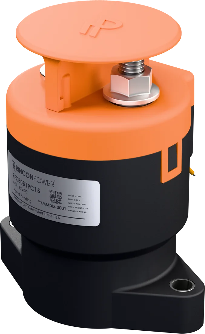
RFC80 FUSETactor, bottom mount, isometric view
Continuous, up to
800 A
Rated voltage
1,000 VDC
Fault trip open
< 3 ms
Interrupt
10 MW+

How it works

A passive fault interrupt, built into the contactor

The FUSETactor switches like a contactor in normal use. When fault current crosses the trip point, it opens on its own, powered by the fault. The clear time does not change with the current.

Fault trip graph Current stays at a normal level. A fault spike rises and crosses the trip line. The FUSETactor opens in under 3 ms and the current falls to zero. TRIP LINE (1.5 TO 3 kA) CURRENT TIME Normal operation OPENS IN < 3 ms Current at zero. Circuit isolated.

Illustration only. Not to scale.

  1. Normal operation

    The FUSETactor carries up to 800 A and switches the circuit like a standard contactor. The integrated coil economizer keeps coil power low.

  2. Fault current

    A fault spike rises above the trip current that you select: 1,500 A, 2,000 A or 2,500 A. Custom tuning from 1.5 to 3 kA is available.

  3. Self-powered trip

    The fault itself powers the trip. The contacts open in under 3 ms, independent of the current. No external power, sensor or controller is required. A trip sense circuit on every unit tells your control system that the FUSETactor has tripped.

Why it matters

One part. Two jobs. Fewer failure points.

No external power

The fault trip is passive and self-powered. It works when the control system does not.

No nuisance trips

No false or nuisance trips. It trips on real fault current, not on noise.

Once it trips, it trips

Non-resettable by design, for safety. A tripped unit cannot close back onto a fault.

Replaces contactor plus fuse

One hermetic, gas-filled ceramic unit does the work of a contactor and a fast fuse.

360° view

Turn it. Tilt it. Zoom in.

Drag to rotate. Pinch or Ctrl + scroll to zoom.

RFC80B1PA15
Loading 360 view
Drag to rotate · Ctrl + scroll or pinch to zoom

Preview frames. Final RFC80 frames load here.

Options

Configure it for your system

Trip current, tuned to your application

We custom tune the trip current to your application, anywhere from 1.5 to 3 kA. Or select a standard trip current: 1,500 A, 2,000 A or 2,500 A.

StandardCustom tuning range

Contact polarity OPTION

POLARITY SENSITIVEBI-DIRECTIONAL

Bi-directional switching is available as an option. Specify it when you order.

Mounting

BOTTOM MOUNTSIDE MOUNT

Two mounting styles for different enclosure layouts.

Coil

12 V DUAL, ECONOMIZED24 V DUAL, ECONOMIZED12 V PWM, EXTERNAL

Integrated coil economizer on the dual-coil versions.

Aux contact and trip sense

A  NOB  NCX  NONE

Optional aux contact (orange wire), linked to the main contacts. Trip sense (blue wire) is standard and opens when the unit trips. White is common.

StateCoilMain contactsTrip sense (blue)
OffOffOpenClosed
Normal operationOnClosedClosed
TrippedOn / OffOpenOpen

Variants

Two form factors. Build your part number.

Bottom mount

SHOWN: RFC80B1PA15
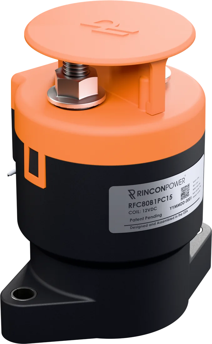
RFC80B1PA15 bottom mount, front isometric view
Part number
RFC80B1PA15
Contact polarity
Mounting
Coil
Aux contact
Trip current
Up to 800 A at 1,000 VDC · Request a quote for this part →

Images show RFC80B1PA15. ## = custom trip current, tuned to your application. The last two digits are the target in kA × 10 (for example 27 = 2.7 kA).
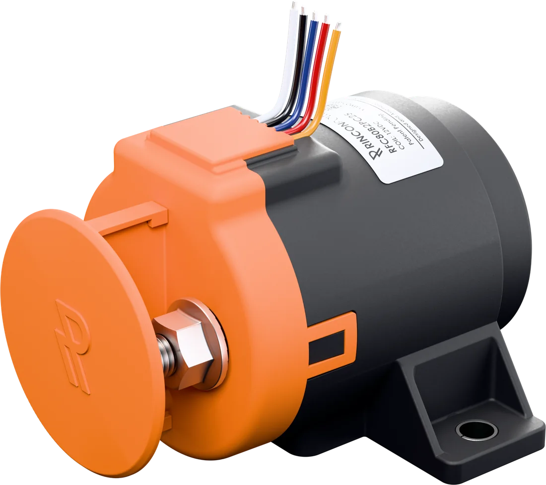
Side mount

SHOWN: RFC80B2PA25
RFC80B2PA25 side mount, front isometric view
Part number
RFC80B2PA25
Contact polarity
Mounting
Coil
Aux contact
Trip current
Up to 800 A at 1,000 VDC · Request a quote for this part →

Images show RFC80B2PA25. ## = custom trip current, tuned to your application. The last two digits are the target in kA × 10 (for example 27 = 2.7 kA).

Key specifications

Sealing
Exceeds IP69K
Hermetic ceramic seal, gas filled
Operating temperature
−40 to 85 °C
170 °C max terminal
Mechanical life
300,000 cycles
Dielectric withstand
4,300 VRMS
60 s, open contacts and contacts to coil
Contact resistance
0.1 to 0.15 mΩ
Typical at 200 A
Shock and vibration
50 G / 15 G
Destructive shock / sinusoidal vibration
Salt fog
MIL-STD-810
Weight
680 g
1.5 lb

All versions: zero back EMF. IEC 60947-4-1 compliant. UL 1007 / UL 1569 lead wires. Data from datasheet Rev 1 (preliminary).

Video

See the FUSETactor

Datasheet and CAD

Download the datasheet and CAD

Fill in three fields to unlock the downloads right away.

Your downloads are ready.

Thank you. Select a file to download.

Sample quote

Request a sample quote

Tell us your application and configuration. We will send you a quote.

Samples are quoted per configuration. Sample deliveries begin in early 2027.

Not sure about a setting? Select "Not sure" and our engineering team will help you configure it.

Contact
Application
Configuration
Contact polarity *
Mounting *
Coil *
Auxiliary contact *
Trip current *
Quantity and timing

Thank you. We received your request.

We will review your configuration and send you a quote. Sample deliveries begin in early 2027.

Your datasheet and CAD downloads are also unlocked.

Go to downloads →